

A 2 mm difference in handmade truffle diameter can become a much larger cavity-clearance problem once packaging manufacturing tolerances are included. For chocolate brands, that difference can determine whether a finished product remains securely positioned or arrives with damaged decorations, missing cocoa powder, or a cracked shell.
The challenge is particularly evident with hand-rolled truffles. Their size and surface texture vary between pieces, while custom inserts are manufactured to defined dimensions. Increasing the cavity opening accommodates larger chocolates but can leave smaller ones with excessive freedom to move.
Effective truffle box insert sizing requires three decisions: how much dimensional variation the cavity must accommodate, where the insert should support the chocolate, and which combination of materials and structure will preserve its appearance throughout packing, storage, and delivery.
Measure the real product range, calculate cavity clearance, control coating loss, choose an insert material based on failure risk, and approve the packaging with repeatable prototype tests before production.
1. Calculate Cavity Clearance and Control Product Variation
The first design decision is to establish the size range that a single cavity must accommodate.
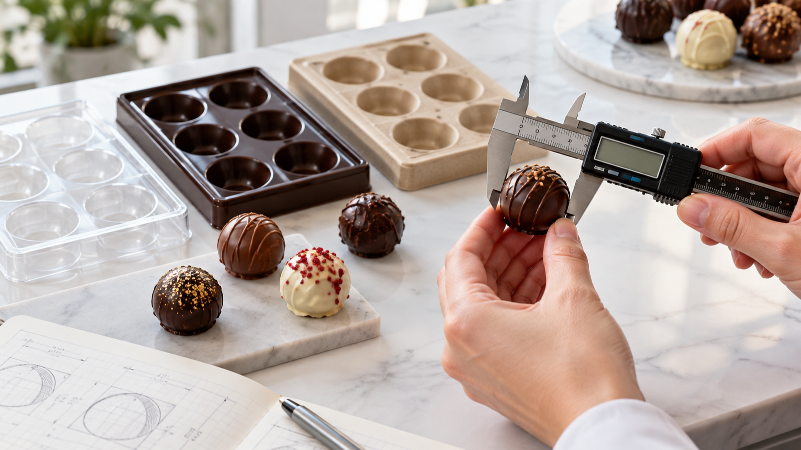
For smooth molded chocolates, measure the finished product after any coating or decoration has been applied. With handmade truffles, measurements should include pieces from different production batches. Record the smallest and largest horizontal dimensions, maximum height, and any fragile projections.
The measurement range becomes the basis for evaluating the combined effects of product variation and insert manufacturing tolerance.
The Tolerance Stack-Up Problem
Consider a batch of hand-rolled truffles with finished diameters ranging from 26 to 28 mm. The packaging designer proposes a nominal circular cavity opening of 30.5 mm, with a manufacturing tolerance of ±0.5 mm.
The cavity opening can therefore range from 30 to 31 mm.
Worked Example: Clearance Across the Full Size Range
| Dimensional Combination | Cavity Opening | Truffle Diameter | Diametrical Clearance |
|---|---|---|---|
| Nominal cavity, largest truffle | 30.5 mm | 28 mm | 2.5 mm |
| Nominal cavity, smallest truffle | 30.5 mm | 26 mm | 4.5 mm |
| Minimum clearance | 30 mm | 28 mm | 2 mm |
| Maximum clearance | 31 mm | 26 mm | 5 mm |
The nominal cavity provides 2.5–4.5 mm of diametrical clearance. When insert manufacturing variation is included, the possible range becomes 2–5 mm.
For a centered circular chocolate, radial clearance is half the diametrical value. In a real insert, however, the chocolate rests against specific parts of the cavity, so actual movement depends on the lower profile and contact points.
The practical check is straightforward: test the largest representative chocolate in a cavity at the smallest permitted opening, then test the smallest product in a cavity at the largest permitted opening.
If smaller truffles move excessively, revise the lower support geometry before simply reducing the opening. Where one cavity cannot accommodate the complete size range without either squeezing large pieces or leaving small pieces unstable, consider tighter product-size controls or separate cavity profiles.
Set Different Clearance Priorities for Different Truffles
| Truffle Type | Initial Prototype Direction | Main Risk |
|---|---|---|
| Smooth molded truffles | Closer cavity profile with controlled side contact | Shell pressure and removal friction |
| Hand-rolled / cocoa-dusted | More open upper cavity with controlled lower support | Powder loss and surface abrasion |
| Decorated truffles | Support the main body while isolating projections | Decoration contact and breakage |
A useful development method is to produce several cavity variants with different openings and lower support profiles. Test all versions with the same chocolate batch. This provides more useful information than adjusting a single diameter repeatedly without knowing which surface is actually causing the problem.
2. Design Cavity Depth and Finger Access Together
The vertical position of a truffle determines how much side support the cavity provides and how easily the consumer can remove it.
For a spherical chocolate with diameter D, its equator is approximately D / 2 above the lowest point. With a 28 mm spherical truffle, that level is approximately 14 mm.
This gives the designer a useful geometric reference. If the rigid cavity wall rises far above the widest section of the chocolate, removal can become more difficult unless adequate access is built into the tray.
Establish the Support Height
A practical starting concept is to keep the main rigid rim below the widest section of an approximately spherical truffle, while using the lower cavity profile to locate the product.
If additional side support is required, use finger-access notches or partial openings rather than surrounding more of the chocolate with a continuous wall.
The final decision should be based on three observations:
- Does the chocolate remain stable during normal handling?
- Can a consumer grasp it without squeezing fragile surfaces?
- Does removal cause visible powder, coating, or decoration loss?
Check Top Clearance in the Fully Assembled Box
Use the tallest finished product, including its highest decorative projection. Place it in the intended cavity, add any glassine sheet, protective pad, or internal cover, and then close the box.
Check the actual distance between the highest point of the chocolate and the component above it. Do not derive this clearance only from the nominal box height.
Test Removal Without Instructions
Give the prototype to several people who were not involved in the packaging design. Ask them to remove the chocolates normally.
Observe where they place their fingers, whether they pinch the shell, whether the chocolate scrapes the sidewall, and whether anyone instinctively turns the package upside down.
Design decision: if removal repeatedly damages the same area, change the access geometry first. Adding more overall clearance may reduce support while leaving the actual interference point unchanged.
3. Calculate Tray Spacing and Assembly Clearance
An insert can fit every truffle correctly and still fail during packing if its overall dimensions are too close to the internal dimensions of the box.
For manual and production-line assembly, the designer must consider cavity pitch, perimeter structure, insert tolerance, box tolerance, and the amount of clearance available when both components reach their dimensional extremes.
From Cavity Dimensions to Overall Tray Size
Continue with the 30.5 mm cavity opening used above. Suppose a 12-piece insert uses three columns and four rows, a 35 mm center-to-center pitch, and a 6 mm perimeter margin.
| Parameter | Dimension |
|---|---|
| Cavity opening | 30.5 mm |
| Center-to-center cavity pitch | 35 mm |
| Space between adjacent openings | 4.5 mm |
| Perimeter margin | 6 mm |
| Nominal layout | 112.5 × 147.5 mm |
For three columns, width is calculated as:
The same logic gives 147.5 mm for four rows.
The tray manufacturer must then add whatever geometry is required for the selected construction: formed sidewalls, flanges, paperboard folds, pulp walls, locking structures, or other assembly features.
Calculate Assembly Clearance at the Worst-Case Limits
Suppose the final insert width is nominally 112.5 mm and the box provides a nominal internal width of 114.5 mm. Nominal total clearance is therefore 2 mm.
If the insert width tolerance is ±0.5 mm and the box internal width tolerance is also ±0.5 mm, calculate the tightest combination:
That leaves only about 0.5 mm per side when the tray is centered.
Whether that is sufficient depends on corner geometry, material stiffness, tray distortion, packing speed, and the way operators insert the tray. Production samples should therefore be assembled repeatedly using components near the dimensional limits, rather than relying only on CAD dimensions.

4. Choose Insert Materials by Their Failure Risks
Material selection should be based on the failure mode that matters most for the product: abrasion, powder transfer, grease staining, dimensional instability, or insufficient structural support.
Thermoformed PET: Powder Adhesion and Surface Contact
Thermoformed PET can create defined cavity shapes and allows customers to see the chocolates clearly. The main design variables include forming depth, draft, material thickness, and the areas where the chocolate touches the tray.
With cocoa-dusted products, visible residue on PET can quickly affect presentation. Fine particles may transfer through direct rubbing and may also be influenced by electrostatic attraction.
Test the actual product against the intended PET grade. Compare the tray immediately after loading, after removal, and after representative handling.
If static attraction is confirmed as a significant contributor, discuss a suitable antistatic resin, additive, or surface treatment with the material supplier. Any material used on a food-contact surface must be appropriate for the intended application.
Molded Pulp: Draft and Surface Friction
Molded pulp supports shaped cavity designs, but the cavity must be compatible with the manufacturing tool and release process.
Draft angle is therefore a practical tooling consideration. Around 5° can be used as an early discussion point for some molded-fiber concepts, while the final geometry should be confirmed by the selected manufacturer according to its tooling and forming process.
Surface finish also matters. Rough fibers can increase friction against cocoa powder, sugar coatings, and delicate chocolate finishes.
For premium products, ask whether the proposed molded-fiber insert can be hot-pressed or otherwise produced with a smoother contact surface, then test it using the actual chocolate.
Paperboard Dividers: Springback and Grease Resistance
Paperboard dividers can be efficient for compartmented chocolate boxes, particularly when each chocolate is additionally supported by a confectionery cup.
The assembled divider should be checked for folding springback. A die-cut layout that appears correct when flat may create narrower compartments after folding if the board resists the intended crease geometry.
Direct chocolate contact introduces a separate grease-resistance requirement.
TAPPI T 559 provides a Kit Test method for comparing the grease resistance of certain paper and paperboard surfaces. A higher Kit value indicates greater resistance to the test solutions, but it does not by itself predict long-term cocoa-butter staining or establish food-contact compliance.
For chocolate packaging, combine the paper specification with an actual storage trial. Place the intended chocolates against the proposed surface and inspect the board for grease staining over the intended evaluation period.
For U.S.-market paper and paperboard food packaging, also verify the proposed coating or grease barrier against applicable FDA food-contact requirements. In January 2025, the FDA announced that 35 food-contact notifications related to PFAS grease-proofing substances for paper and paperboard packaging were no longer effective.
For EU-bound packaging, food-contact materials must meet the applicable requirements of Regulation (EC) No 1935/2004. Plastic food-contact inserts are additionally subject to relevant requirements under Regulation (EU) No 10/2011.
5. Use a Focused Prototype Test to Find Packaging Failures
A useful prototype test does not need dozens of loosely defined checks. It needs a small number of repeatable tests that reveal how and where the packaging fails.
Test 1: Fit, Removal, and Inversion
Load representative chocolates covering the approved size range, including large pieces, small pieces, and those with fragile decoration.
Remove several chocolates and inspect for scraping, powder loss, shell pressure, and difficult finger access.
Then assemble the box with its intended protective components, carefully invert it over a protected surface, return it upright, and inspect the products again.
Look for:
- Product displacement between cavities
- Cocoa or cinnamon powder deposited on the tray walls
- Decorations contacting the lid or neighboring products
- Cracked shells
- Insert deformation
If a protective top sheet or cushion is used, test it as part of the complete system. Glassine can provide separation, but it should not be treated as an impact-absorbing cushion unless the structure has been specifically designed and validated for that purpose.
Test 2: Distribution Handling
For parcel-delivered chocolate boxes, create a repeatable handling test that reflects the actual route to the customer. Record the drop orientation, height, number of drops, and inspection criteria.
When formal parcel-distribution testing is required, ISTA 3A provides a standardized framework for individual packaged products weighing 70 kg / 150 lb or less.
The chocolate itself is the primary inspection object. An outer box can remain intact while the chocolates inside move, crack, lose coating, or damage their decorations.
Test 3: Grease and Storage Stability
For paper-based inserts or dividers, compare the intended materials using the actual chocolate product.
A 40°C exposure can be used as an accelerated material-screening condition when the objective is to compare grease-barrier behavior. Keep that test separate from finished-product shelf-life validation because 40°C is far above normal chocolate storage conditions.
The assembled retail package should instead be evaluated under the storage conditions specified for the chocolate.
During the trial, inspect for:
- Visible grease staining
- Powder or coating transfer
- Moisture-related paper deformation
- Tray warping
- Changes in fit after storage
Keep one approved physical sample together with the final dimensions, material specification, and agreed inspection criteria. Future production can then be checked against an actual accepted reference instead of relying on memory or photographs.

6. Prepare the Supplier Specification Before Ordering
Once the cavity structure and material direction are established, consolidate the project information into one specification before requesting production tooling or a bulk quotation.
| Specification | Information to Provide |
|---|---|
| Product type | Molded, hand-rolled, cocoa-dusted, decorated, or mixed assortment |
| Finished dimensions | Minimum and maximum horizontal dimensions plus maximum height |
| Surface condition | Powder coating, nuts, sugar, smooth shell, or fragile decoration |
| Quantity per box | Number of pieces and preferred arrangement |
| Insert material | Paperboard, molded pulp, PET, or functional requirements |
| Existing outer box | Actual usable internal length, width, and height |
| Food-contact condition | Direct contact or individually wrapped / cupped product |
| Distribution | Retail pickup, local delivery, or parcel shipping |
| Target market | Destination country or region |
| Supporting files | Product photos, CAD drawings, existing packaging, and physical samples where available |
For an existing box, provide actual internal measurements rather than relying only on the nominal box specification.
For a new project, designing the insert and outer box together gives the packaging supplier more flexibility to optimize cavity spacing, tray dimensions, presentation, and assembly.
DeChen Printing can review chocolate dimensions, desired box capacity, material requirements, and reference packaging during custom chocolate packaging development.
Frequently Asked Questions
How Can I Stop Cocoa Powder or Cinnamon from Collecting Inside the Insert?
First identify when the residue appears. Powder deposited during loading usually points to cavity contact or a narrow opening. Residue that becomes worse after handling indicates repeated movement between the chocolate and the tray.
With PET, electrostatic attraction may contribute to visible powder adhesion. With molded pulp or paper structures, surface friction can be more important. Compare several materials and cavity profiles using the same batch of truffles before changing the entire packaging structure.
If My Handmade Truffles Vary by ±2.5 mm, Should I Use Custom Inserts or Individual Glassine Cups?
A ±2.5 mm variation creates a total size range of 5 mm. Close-fitting molded cavities become harder to optimize because the cavity must accommodate the largest pieces without leaving excessive movement around smaller ones.
Individual confectionery cups can provide more tolerance for variable handmade products. Compare this option with custom cavities based on presentation, product movement, filling labor, tooling cost, order quantity, and the amount of positioning control required.
How Much Clearance Should I Leave Between the Insert and the Outer Box?
Calculate clearance using the largest permitted insert and the smallest permitted internal box dimensions.
For example, a 112.5 mm insert inside a 114.5 mm box provides 2 mm nominal total clearance. If both dimensions carry ±0.5 mm tolerances, the worst-case combination leaves only 1 mm total clearance. Test representative samples at these dimensional extremes to confirm that assembly remains reliable.
Design the Insert Around the Chocolate, Not Just Its Diameter
Reliable truffle packaging starts with the finished product's dimensional range, surface condition, support geometry, and real distribution requirements. Cavity clearance, material selection, tray layout, and outer-box fit should then be verified through physical samples.
If you are developing a new truffle box, send DeChen Printing your product dimensions, quantity per box, photos, material preferences, and any existing packaging specifications. These details provide the basis for discussing insert structure and sample development.
Get a Custom Quote